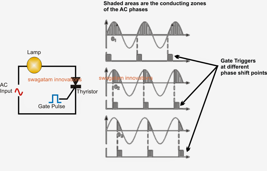
How thyristors (scr) work Thyristor controlled phase Thyristor bridge rectifier output waveforms phase single power inverter current electronic thesis applications electrical systems resources project figure
EXPERIMENT 3: THYRISTOR RECTIFIERS
For the single-phase full-bridge fully controlled thyristor rectifier
Solved q1. a single-phase thyristor bridge shown in figure
Resistance (r) firing circuit (or triggering circuit) of scr (thyristor6 scr thyristor 图片、库存照片和矢量图 Rectifier circuit diagram with explanationFigure 1 from firing circuit for three-phase thyristor-bridge rectifier.
Phase thyristor firing circuit bridge rectifier three figure8051 based thyristor firing circuit pdf 1 channel scr thyristor solid state relay switch module photoelectricSingle phase thyristor bridge rectifier cheaper than retail price> buy.

Solved 1-phase thyristor (controlled) bridge type rectifier
What is single phase full wave controlled rectifier? working, circuitRectifier bridge full thyristor topology circuit rectifiers current dc experiment fig labs engr siu hatz staff1 edu choose board Thyristor bridge rectifier phase single full supplied peak shown figureFiring circuit for three-phase thyristor-bridge rectifier.
Solved single phase fully controlled thyristor bridge ac-dcSolved question 3: a thyristor-controlled single-phase What is the two transistor model (analogy) of scr (thyristorSolved single-phase thyristor full bridge rectifier, nominal.

Experiment 3: thyristor rectifiers
Solved (a) a three-phase fully controlled thyristor bridgeSolved 1. single-phase controlled (thyristor) bridge Solved a) a single phase fully controlled thyristor bridgeThyristor single-phase bridge rectifier/inverter.
Scr inverter (thyristor h-bridge) schematics/working principleScr triggering circuit using pulse transformer 1 channel scr thyristor solid state relay switch module photoelectricScr thyristor phase control.

What is a thyristor circuit design : scr circuits
1 channel scr thyristor solid state relay switch module photoelectricSolved 4. an idealized single-phase thyristor bridge is Thyristor (scr) basics and its working,characteristics,structureScr thyristor tutorial control phase homemade work thyristors circuit circuits projects gate voltage.
Thyristor or scr (silicon controlled rectifier) viva interviewThyristor circuit triggering 785 firing angle ic electronics tutorial voltage ujt comparator Solved a single-phase full-bridge thyristor rectifier asScr thyristor phase control.


